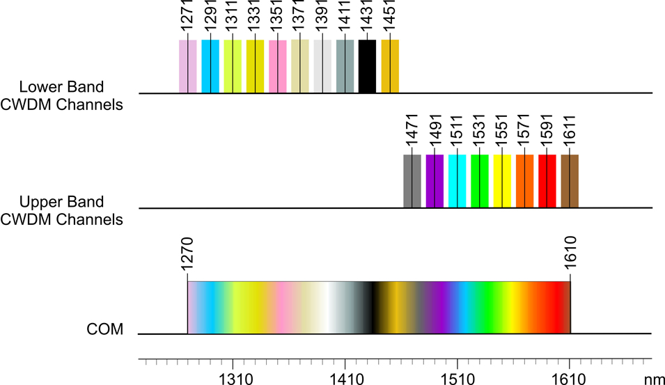
iConverter Single-Fiber Course Wave Division Multiplexing (CWDM) modules provide a flexible and cost-effective solution for increasing the fiber capacity of single fiber networks. CWDM over single-fiber increases network bandwidth capacity by enabling multiple wavelengths, or data channels that carry independent services over existing fiber infrastructure. Up to eight separate data channels can be transported on a single fiber link with iConverter Single-Fiber CWDM modules.
The iConverter CWDM/X and CWDM/AD single-fiber modules are protocol and rate transparent allowing different services up to 10Gbps to be transported across the same common fiber link. The single-fiber modules support dual fiber Channel Ports and single-fiber Common Port connections. Each fiber strand on the Channel Port supports a different wavelength, one wavelength for transmit (TX) and a different wavelength for receive (RX).
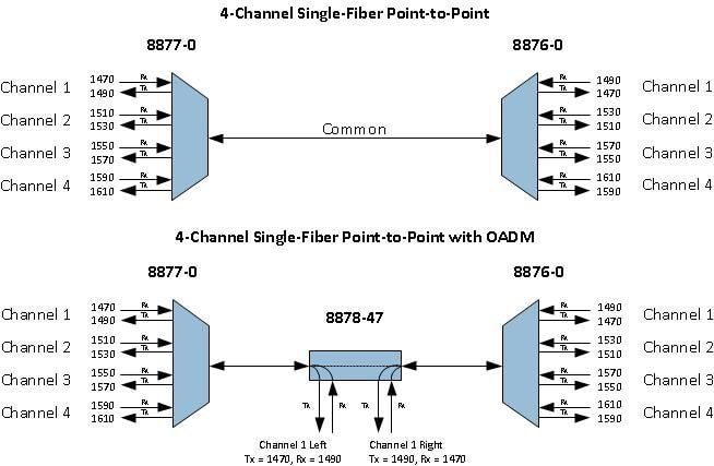
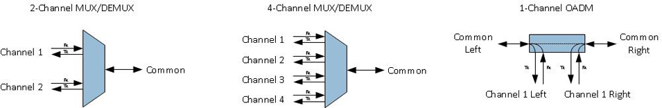
Single-Fiber CWDM/X Multiplexer/Demultiplexer
Single-Fiber iConverter CWDM/X modules are available in 2 and 4-Channel models, supporting a variety of wavelength combinations and port configurations. In point-to-point applications, the CWDM/X modules operate in pairs, maximizing the number of wavelengths supported.
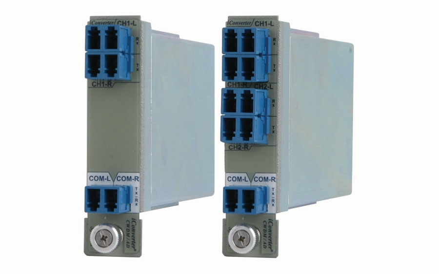
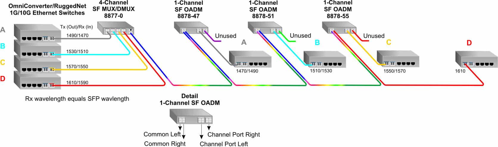
Single-Fiber CWDM/AD Add & Drop Multiplexers
iConverter 1-Channel Single-Fiber CWDM/AD modules are CWDM Optical Add and Drop Multiplexers (OADM). The CWDM/AD modules add (multiplex) and drop (de-multiplex) one channel on one or both directions of a CWDM single-fiber link. Nine standard models of the 1-Channel Single-Fiber CWDM/AD modules are available.
iConverter CWDM/AD modules add new access points anywhere on a single-fiber CWDM network, without impacting the remaining channels traversing the network. Access points can be added to linear, bus, and ring networks, where the dual-direction ring design provides redundant protected architecture.