Main Menu
Useful Links
Contact us
Follow us
© 2025 Omnitron Systems Technology, Inc. All Rights Reserved. | Privacy Policy

*100Mbps supported with 100M SGMII SFP Transceivers
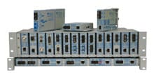
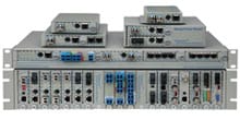
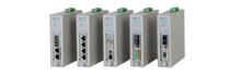
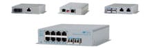
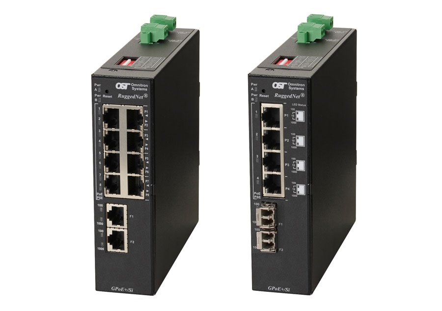
The RuggedNet GPoE+/Si is a unmanaged Industrial PoE and PoE+ Ethernet switch that features fiber or copper uplink ports and four or eight 10/100/1000 PoE/PoE+ RJ-45 copper user ports.
The RuggedNet GPoE+/Si is a standard Layer 2 Ethernet switch that forwards frames to any port based on their MAC address.
The RuggedNet GPoE+/Si supports Directed Switch mode, which directs multicast traffic (such as video) only to the appropriate uplink port, preventing the multicast video traffic from flooding other network ports.
Models with two fiber or two copper uplink ports support daisy-chain configurations or redundant uplinks for critical applications that require protection and sub 50ms restoration in the event of an uplink failure.
Models with two fiber or two copper uplink ports also support Dual Device mode that enables the GPoE+/Si to operate as two independent and isolated Ethernet switches. In Dual Device mode, the GPoE+/Si provides separate and independent data traffic paths between the two uplink ports and four or eight user ports.
The RuggedNet GPoE+/Si modes of operation can be configured using easily accessible DIP-switches. Each DIP-switch function is labeled on the top of the RuggedNet for ease of identification and use.
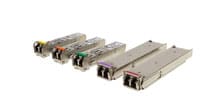
The RuggedNet GPoE+/Si is available with fixed ST, SC, and LC connectors or Small Form Pluggable (SFP) transceivers. Fiber ports support multimode or single-mode and dual fiber or single-fiber with distances up to 140km. SFP models support a variety of distances in standard, CWDM and DWDM wavelengths.
The switches feature a PoE power reset function that enables the attached PD device, such as a camera or access point, to be re-initialized remotely, eliminating the need for costly truck rolls to remote PD sites. When a problem with a PD is detected, the fiber port on the module can be disconnected, triggering the PoE power reset function.
All models can be wall or rack mounted using a wall mount bracket and shelf or DIN-rail mounted using the included DIN-rail mounting clip. They are available with single or dual DC input power options.
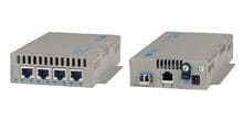
Daisy Chain Application
This example demonstrates the daisy chain capabilities of the RuggedNet PoE switches. In this application each RuggedNet switch connects to its neighboring switch via its uplink ports. The daisy chain can continue to additional switches using this method of connectivity.
Each RuggedNet switch provides connectivity to the fiber links, and power to IP cameras and Wi-Fi access points at each location along the daisy chain.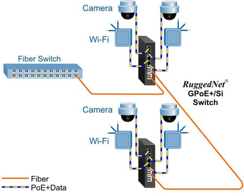
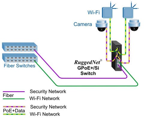
Dual Device Mode
This Dual Device feature is extremely useful when two isolated networks domains share a single network distribution location.
The example below depicts a scenario where a surveillance security (purple) network and a Wi-Fi (green) network are sharing a single hub distribution location. Using the two uplinks and the Dual Switch mode facilitates using a single PoE switch driving both the Cameras and the Wi-Fi Access Points while maintaining isolation between the networks.
| Description | RuggedNet® GPoE+/Si 10/100/1000BASE-T with Gigabit Fiber or 10/100/1000BASE-T Copper Uplinks Ruggedized Unmanaged PoE+ Ethernet Switch |
|
|---|---|---|
| Standard Compliances | IEEE 802.3, IEEE 802.3af (15.40 watts), IEEE 802.3at (30 watts) | |
| Regulatory Compliances |
Safety: UL 62368-1, UL 60950-1, IEC 62368-1, IEC 60950-1, EN 62368-1, EN 60950-1, CAN/CSA C22.2 No. 62368-1-14, CAN/CSA C22.2 No. 60950-1, CE Mark, UKCA EMC: EN 55032/24 CE Emissions/Immunity, IEC 61000-6-4 Industrial Emissions, IEC 61000-6-2 Industrial Immunity EMI: CISPR 32, FCC 47 Part 15 Subpart B Class A EMS: IEC 61000-4-2 ESD: Contact: 6 kV; Air: 8 kV, IEC 61000-4-3 RS: 80 MHz to 1 GHz: 10 V/m (on UTP cabling) and 20 V/m (on STP cabling) IEC 61000-4-4 EFT: Power: 2 kV; Signal: 1 kV, IEC 61000-4-5 Surge: Power: 2 kV; Signal: 2 kV, IEC 61000-4-6 CS: Signal: 10 V, IEC 61000-4-8 ( Magnetic Field), 30A/m, IEC 61000-4-11 (General Immunity in Industrial Environments) IP Rating: IP40 Protection ACT: TAA, BAA, NDAA |
|
| Environmental | REACH, RoHS and WEEE | |
| PoE Modes | IEEE Alternate A (Alt A) | |
| Frame Size | Up to 10,240 bytes | |
| Port Types |
Copper: RJ-45: 10/100/1000BASE-T Fiber: Fixed: ST, SC, LC 1000BASE-X Fiber SFP: 10/100/1000BASE-T SGMII Copper Transceiver or 100BASE-X SGMII Fiber Transceiver or 1000BASE-X SERDES Fiber Transceivers |
|
| Cable Types | Copper: EIA/TIA 568A/B, Cat 5 UTP and higher Fiber: Multimode: 50/125, 62.5/125µm Single-mode: 9/125µm |
|
| DC Power Requirements | 4 RJ-45 Ports: +46 to +57VDC; 2.31A @ 56VDC 2 Pin Terminal (isolated) |
8 RJ-45 Ports: +46 to +57VDC; 4.47A @ 56VDC 2 Pin Terminal (isolated) |
| Dimensions (W x D x H) |
1.5” x 5.5” x 5.5” (38.1 mm x 139.7 mm x 139.7 mm) | |
| Weight | 4 RJ-45 Ports: 1.70 lb.; 772 grams |
8 RJ-45 Ports: 1.77 lb.; 803 grams |
| Operating Temperature | Extended: -40 to 75°C Storage: -40 to 80°C |
|
| Humidity | 5% to 95% (non-condensing) | |
| Altitude | -100m to 4,000m (operational) | |
| MTBF (hrs) | 278,000 | |
| Warranty |
5 year product warranty with 24/7/365 free Technical Support
|
|
| Description | IEEE 802.3af PoE | IEEE 802.3at PoE+ |
|---|---|---|
| Power Supply Voltage Range | 46.0 to 57.0 VDC | 51.0 to 57.0 VDC |
| Voltage Range at PSE port Output | 44.0 to 56.0 VDC | 50.0 to 56.0 VDC |
| Maximum Power from PoE/PSE port | 15.4 watts | 30 watts |
| Minimum Voltage at PoE/PD port input* | 37.0 VDC | 42.5 VDC |
| Minimum Power at PoE/PD port* | 12.95 watts | 25.5 watts |
| * at 100 meters using Cat5 | ||
| RuggedNet GPoE+/Si Models | |||||||||||||
|---|---|---|---|---|---|---|---|---|---|---|---|---|---|
| Fiber Type | Distance | Connector Type | Tx/Rx Lambda (nm) | Min. Tx Power (dBm) | Max. Tx Power (dBm) | Min. Rx Power (dBm) | Max. Rx Power (dBm) | Min Atten (dB) | Link Budget (dB) | ||||
| ST | SC | LC | SFP | RJ-45 | |||||||||
| MM/DF | 220/550m1 | 9560-0-1y-pZ | 9562-0-1y-pZ | 9566-0-1y-pZ | - | - | 850/850 | -10 | -4 | -17 | -3 | - | 7 |
| MM/DF (x2) | 220/550m1 | - | - | 9566-0-2y-pZ | - | - | 850/850 | -10 | -4 | -17 | -3 | - | 7 |
| MM/DF | 2km | - | 9562-6-1y-pZ | - | - | - | 1310/1310 | -9.5 | -3 | -19.5 | -3 | - | 10 |
| SM/DF | 12km | 9561-1-1y-pZ | 9563-1-1y-pZ | 9567-1-1y-pZ | - | - | 1310/1310 | -9.5 | -3 | -19.5 | -3 | - | 10 |
| SM/DF (x2) | 12km | - | - | 9567-1-2y-pZ | - | - | 1310/1310 | -9.5 | -3 | -19.5 | -3 | - | 10 |
| SM/DF | 34km | - | 9563-2-1y-pZ | - | - | - | 1310/1310 | -5 | 0 | -23 | -3 | 3 | 18 |
| SM/DF | 80km | - | 9563-3-1y-pZ | - | - | - | 1550/1550 | -5 | 0 | -23 | -3 | 3 | 18 |
| SM/DF | 110km | - | 9563-4-1y-pZ | - | - | - | 1550/1550 | 0 | 5 | -24 | -3 | 8 | 24 |
| SM/DF | 140km | - | 9563-5-1y-pZ | - | - | - | 1550/1550 | 2 | 5 | -28 | -8 | 13 | 30 |
| MM/SF2 | 220/550m1 | - | 9570-0-1y-pZ | - | - | - | 1310/1550 | -9 | -3 | -18 | -3 | - | 9 |
| MM/SF2 | 220/550m1 | - | 9571-0-1y-pZ | - | - | - | 1550/1310 | -9 | -3 | -18 | -3 | - | 9 |
| SM/SF2 | 20km |
- | 9570-1-1y-pZ | - | - | - | 1310/1550 | -9.5 | -3 | -20 | -3 | - | 10.5 |
| SM/SF2 | 20km |
- | 9571-1-1y-pZ | - | - | - | 1550/1310 | -9.5 | -3 | -20 | -3 | - | 10.5 |
| SM/SF2 | 40km |
- | 9570-2-1y-pZ | - | - | - | 1310/1550 | -3 | 0 | -20 | -3 | 3 | 17 |
| SM/SF2 | 40km |
- | 9571-2-1y-pZ | - | - | - | 1550/1310 | -3 | 0 | -20 | -3 | 3 | 17 |
| SFP (x1) | - | - | - | - | 9579-0-1y-pZ | - | - | - | - | - | - | - | - |
| SFP (x2) | - | - | - | - | 9579-0-2y-pZ | - | - | - | - | - | - | - | - |
| RJ-45 (x2) | 100m | - | - | - | - | 9579-1-2y-pZ | - | - | - | - | - | - | - |
|
1 62.5/125µm, 100/140µm multimode fiber up to 220m. 50/125µm multimode fiber up to 550m. 2 When using single-fiber (SF) models, the Tx wavelength on one end has to match the Rx wavelength on the other. MM = Multimode, SM = Single-mode, DF = Dual Fiber, SF = Single-fiber Contact Omnitron for other fiber options. Order the appropriate SFPs separately. Visit the Optical Transceivers web page. |
|||||||||||||
| 4 = Four RJ-45 Ports |
| 8 = Eight RJ-45 Ports |
| 1 = Single DC 2-Pin Terminal Power Connector |
| 2 = Dual DC 2-Pin Terminal Power Connectors |
| Z = Extended temperature (-40 to 75°C) |
| Model Number | Description | 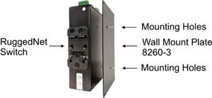 |
|---|---|---|
| 8260-3 | Wall Mounting Plate | |
| 8260-0 | 19" rack mount shelf |
| Model | Product Operating Temperature Range | Watts Required | Industrial Power Supply Model |
|---|---|---|---|
| -25 to 70C | |||
| GPoE+/Si 4 Port | Commercial / Wide / Extended | 130 watts | 9170-PS-240 |
| GPoE+/Si 8 Port | Commercial / Wide / Extended | 250 watts | 9170-PS-480 |
RuggedNet GPoE+/Si (Datasheet)
RuggedNet GPoE+/Si (User Manual)
Wall Mount Plate (User Manual)
9170-PS-480 Industrial Power Supply (Datasheet)
9170-PS-240 Industrial Power Supply (Datasheet)
9560-0-14-1Z, 9560-0-14-2Z, 9561-1-14-1Z, 9561-1-14-2Z, 9562-0-14-1Z, 9562-0-14-2Z, 9562-6-14-1Z, 9562-6-14-2Z, 9563-1-14-1Z, 9563-1-14-2Z, 9563-2-14-1Z, 9563-2-14-2Z, 9563-3-14-1Z, 9563-3-14-2Z, 9563-4-14-1Z, 9563-4-14-2Z, 9563-5-14-1Z, 9563-5-14-2Z, 9566-0-14-1Z, 9566-0-14-2Z, 9566-0-24-1Z, 9566-0-24-2Z, 9567-1-14-1Z, 9567-1-14-2Z, 9567-1-24-1Z, 9567-1-24-2Z, 9570-0-14-1Z, 9570-0-14-2Z, 9571-0-14-1Z, 9571-0-14-2Z, 9570-1-14-1Z, 9570-1-14-2Z, 9571-1-14-1Z, 9571-1-14-2Z, 9570-2-14-1Z, 9570-2-14-2Z, 9571-2-14-1Z, 9571-2-14-2Z, 9579-0-14-1Z, 9579-0-14-2Z, 9579-0-24-1Z, 9579-1-24-1Z, 9579-0-24-2Z, 9579-1-24-2Z, 9560-0-18-1Z, 9560-0-18-2Z, 9561-1-18-1Z, 9561-1-18-2Z, 9562-0-18-1Z, 9562-0-18-2Z, 9562-6-18-1Z, 9562-6-18-2Z, 9563-1-18-1Z, 9563-1-18-2Z, 9563-2-18-1Z, 9563-2-18-2Z, 9563-3-18-1Z, 9563-3-18-2Z, 9563-4-18-1Z, 9563-4-18-2Z, 9563-5-18-1Z, 9563-5-18-2Z, 9566-0-18-1Z, 9566-0-18-2Z, 9566-0-28-1Z, 9566-0-28-2Z, 9567-1-18-1Z, 9567-1-18-2Z, 9567-1-28-1Z, 9567-1-28-2Z, 9570-0-18-1Z, 9570-0-18-2Z, 9571-0-18-1Z, 9571-0-18-2Z, 9570-1-18-1Z, 9570-1-18-2Z, 9571-1-18-1Z, 9571-1-18-2Z, 9570-2-18-1Z, 9570-2-18-2Z, 9571-2-18-1Z, 9571-2-18-2Z, 9579-0-18-1Z, 9579-0-18-2Z, 9579-0-28-1Z, 9579-1-28-1Z, 9579-0-28-2Z, 9579-1-28-2Z,
Main Menu
Useful Links
Contact us
Follow us
© 2025 Omnitron Systems Technology, Inc. All Rights Reserved. | Privacy Policy
