CWDM Multiplexer | iConverter CWDM MUX CWDM Multiplexer | iConverter CWDM MUX
iConverter® CWDM/X


4 and 8 Channel Multiplexer/Demultiplexer

Omnitron’s iConverter CWDM/X Coarse Wave Division Multiplexing (CWDM) Multiplexer/Demultiplexer (MUX/DEMUX) modules support ITU-T G.694.2 wavelengths between 1270nm to 1610nm in 20nm increments. iConverter CWDM/X modules are protocol and rate transparent allowing different services up to 10Gbps to be transported across the same fiber link.


Features


  • 4 and 8 channels multiplexer/demultiplexer modules
  • Scalable to 8 or 16 channels using an optional Expansion Port or separate Band Splitter
  • Enables existing 1310nm networks to carry up to an additional 8 channels with optional 1310nm Pass Band Port
  • Enables existing 1550nm networks to carry up to an additional 4 channels with optional 1550 Pass Band/ Expansion Port
  • Protocol and rate transparent up to 10Gbps
  • Highly compact form factor with up to 120 ports in a 2U chassis
  • Seamless integration with other iConverter media converters and chassis for multi-service platforms
  • Compatible with LGX chassis using the iConverter LGX Adapter
  • Passive device that can also be installed in a powered chassis for managed applications
  • Management available with the addition of a management module to the chassis
  • Minimal and uniform optical loss facilitates easy network planning
  • Industry standard LC UPC or APC connectors
  • Commercial (0 to 50°C) and wide (-40 to 60°C) temperature ranges
  • One (1) Year Warranty and Free 24/7 Technical Support


Description


Coarse Wave Division Multiplexing (CWDM) is a technology which multiplexes a number of optical signals onto a single fiber by using different wavelengths of light.

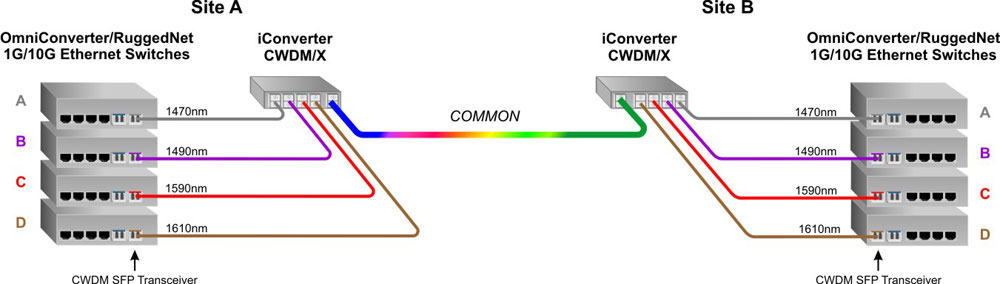
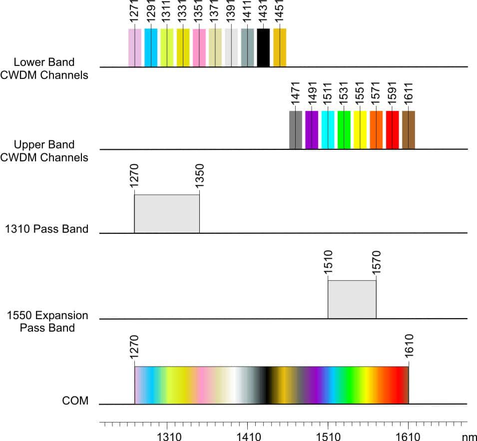
Omnitron’s iConverter CWDM/X Multiplexer/Demultiplexer (MUX/DEMUX) modules support ITU-T G.694.2 wavelengths between 1270nm to 1610nm in 20nm increments. CWDM/X modules are protocol and rate transparent allowing different services up to 10Gbps to be transported across the same fiber link.

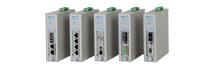
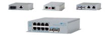
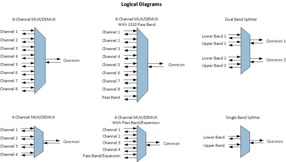
The passive CWDM/X modules are available in 4 and 8-Channel (wavelength) models, supporting a variety of wavelength combinations and port configurations.

The 4-Channel CWDM/X features an optional 1550 Pass Band/Expansion Port that can be used to cascade two MUX/DEMUX modules, doubling the channel capacity on the common fiber link or overlay four CWDM channels on the existing 1550nm network.

The 4 and 8-Channel MUX/DEMUX modules feature an optional 1310nm Pass Band port that allows up to eight CWDM channels to be overlaid on an existing 1310nm network.

Two 8-Channel MUX/DEMUX modules can be cascaded to create a 16-Channel common fiber link using the CWDM/X Band-Splitter. The Band-Splitter module combines and separates the lower CWDM channels (1270nm to 1450nm) and the upper CWDM channels (1470nm to 1610nm).

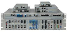
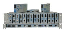
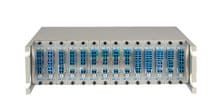
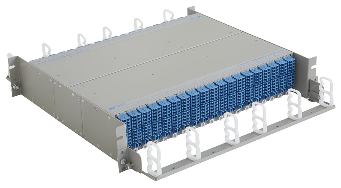
The small and compact size of the CWDM/X modules yields one of the highest port densities in the industry. Using the 2U high iConverter compact chassis, 38 CWDM/X modules can be installed, providing up to 684 connectors or up to 608 simplex channels or 304 duplex channels.

iConverter_19-Module_Compact_Chassis_CWDM_DS.jpg

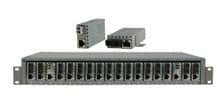
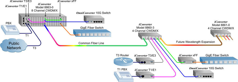
iConverter CWDM/X modules can be installed in any iConverter chassis equipped with other iConverter media converters and transponders to provide a multi-service platform capable of delivering Ethernet, TDM, SONET and other services across a CWDM fiber common link.


Examples


Multi-Service CWDM Application

This example shows a multiple channel multiplexing/ demultiplexing application. The iConverter 19-module chassis at the top of the illustration is providing a multi-service platform in which the traffic from external T1/E1, T3/E3 and 10Gbps Ethernet sources are converted from copper-tofiber or fiber-to-fiber using iConverter media converters. Each converter is equipped with the appropriate CWDM channel Small Form Pluggable (SFP) fiber transceiver. The traffic from a fiber port on the Gigabit Ethernet switch is converted from its standard 1310nm wavelength to the appropriate CWDM channel using an iConverter xFF fiber-to-fiber transponder.

All four channels are connected to corresponding channels on a 8-Channel multiplexer, which are multiplexed over a fiber common link to the remote 4-Channel multiplexer. At the remote locations, the four channels are converted back to their original copper and fiber media using standalone converters. The example also shows the addition of four extra channels using the Expansion Ports on the remote CWDM/X. The 8865-0 Band-Splitter (not shown) can also be used.

CWDM X App B

Point to Point CWDM

In this application, the customer needs to transport four (4) independent 10G Ethernet switches from Site A to Site B over a single-mode dual fiber infrastructure. Each switch at Site A is connected with its peer at Site B. A four (4) channel CWDM Multiplexer is use to connect the switches to the existing single-mode fiber. The CWDM Multiplexer will multiplex the four independent switches onto the existing single-mode fiber network.

The switches at Site A and B can be co-located or located in different MDF/IDFs within the customer’s premise. To connect the switches to the CWDM Multiplexer, CWDM Small Form Pluggable (SFP) transceivers are installed in each 10G switch. The wavelength of each SFP transceiver will match the wavelength of the channel port on the CWDM Multiplexer as well as the wavelength of the SFP transceiver in the peer switch.

As shown in the diagram, switch A at Site A has a 1470nm CWDM SFP transceiver installed. A single-mode fiber patch cord connects the transceiver to the 1470nm channel port on the four (4) channel CWDM Multiplexer. At Site B, switch A also has a 1470nm CWDM SFP transceiver installed and connected to the 1470nm channel port on the CWDM Multiplexer. Each switch at Site A has a corresponding CWDM SFP transceiver installed to match the channel port on the CWDM Multiplexer and peer switch at Site B.

The fiber capacity in this application can be increased to sixteen (16) channel using a combination of different CWDM Multiplexers and Band Splitters.

4 Channel CWDM Diagram


Specifications


Description
 iConverter CWDM/X
 4 and 8 Channel Multiplexer/Demultiplexer
Regulatory Compliances
Safety:
EMI:
UL, CE, UKCA
FCC Class A
Environmental RoHS, WEEE, REACH
Port Types
Fiber: 
4 Channels: LC (UPC)
8 Channels: LC (UPC or APC)
Optional 1310 Pass Band: LC (UPC or APC) 
Optional Expansion Port: LC (UPC)
Cable Types
Fiber: 
Single-mode: 9/125μm
Channel Ports: Dual Fiber
Common Port: Dual Fiber
DC Power Requirements
DC Input: 
(Backplane) 
3.3VDC, 0.025A @ 3.3VDC
(when management is required, otherwise passive operation)
Dimensions
W x D x H
0.85” x 4.5” x 2.8” (21.6 mm x 114.3 mm x 71.1 mm)
Weight
12 oz. (340.2 grams)
Temperature
Commercial:
Wide:
Storage:
    0 to 50°C
 -40 to 60°C
 -40 to 80°C
Humidity
 5% to 95% (non-condensing)
Altitude
 -100m to 4,000m (operational)
MTBF (hrs)
> 1,000,000
Warranty
One (1) year warranty with 24/7/365 free Technical Support


Optical Characteristics
ParameterUnitsValues
Common Port
Operating Wavelength
nm 1270 - 1610
CWDM Center Channel nm
1271, 1291, 1311, 1331, 1351, 1371, 1431, 1451, 1431, 1451, 1471, 1491, 1511, 1531, 1551, 1571, 1591, 1611
CWDM Channel Spacing nm 20
1310 Pass Band nm 1270 - 1350
1310 Pass Band Width nm ± 6.5
1550 Pass Band/Expansion nm 1510 - 1570
1310 Pass Band Width dB ± 6.5
4-Channel Insertion Loss dB < 1.9
4-Channel Insertion Loss with
Pass Band or Expansion
dB < 2.0
8-Channel Insertion Loss dB < 2.7
Band Splitter Insertion Loss dB < 0.8
Adjacent Channel Isolation dB > 30
Non-Adjacent Channel Isolation
4 and 8-Channel
dB > 40
Non-Adjacent Channel Isolation
Band Splitter
- N/A
Return Loss (filtered channel) dB ≥ 45


Wavelengths


Ordering


Step 1: Choose a Base Part Number (xxxx-xt)

Model NumberModel TypeChannel Port
ITU Center Wavelengths (nm)
8860-0t 4-Channel MUX/DEMUX with LC UPC Connectors 1471, 1491, 1591, 1611
8860-1t 4-Channel MUX/DEMUX and 1310 Pass Band with LC UPC Connectors 1471, 1491, 1591, 1611
8860-2t 4-Channel MUX/DEMUX, 1310 Pass Band and 1550 Pass Band/Expansion with LC UPC Connectors 1471, 1491, 1591, 1611
8860-3t 4-Channel MUX/DEMUX and 1550 Pass Band/Expansion with LC UPC Connectors 1471, 1491, 1591, 1611
8861-0t 4-Channel MUX/DEMUX with LC UPC Connectors 1511, 1531, 1551, 1571
8861-1t 4-Channel MUX/DEMUX and 1310 Pass Band with LC UPC Connectors 1511, 1531, 1551, 1571
8862-0t 8-Channel MUX/DEMUX with LC UPC Connectors 1271, 1291, 1311, 1331, 1351, 1371, 1431, 1451
8863-0t 8-Channel MUX/DEMUX with LC UPC Connectors 1471, 1491, 1511, 1531, 1551, 1571, 1591, 1611
8863-5t 8-Channel MUX/DEMUX with LC APC Connectors 1471, 1491, 1511, 1531, 1551, 1571, 1591, 1611
8863-1t 8-Channel MUX/DEMUX and 1310 Pass Band with LC UPC Connectors (occupies two slots in the chassis) 1471, 1491, 1511, 1531, 1551, 1571, 1591, 1611
8863-6t 8-Channel MUX/DEMUX and 1310 Pass Band with LC APC Connectors (occupies two slots in the chassis) 1471, 1491, 1511, 1531, 1551, 1571, 1591, 1611
8865-0t Single Band Splitter Lower Band (1271 - 1451) + Upper Band (1471 - 1611)
8865-2t Dual Band Splitter Lower Band (1271 - 1451) + Upper Band (1471 - 1611)

1310 Pass Band port supports 1260nm to 1460nm (Rev 2.0 or later). The port can be used to cascade two 8-Channel MUX or pass any legacy 1310 device.

1550 Pass Band / Expansion port supports 1510nm to 1570nm. The port can be used to cascade the two 4-Channel MUX or pass any legacy 1550 device.

Contact Omnitron for other port configurations, extended temperature (-40 to 75°C) and RoHS (5/6) compliant models.

See chassis and mounting options at: iConverter Chassis and Mounting Option web page

Step 2: Choose an Operating Temperature Option (xxxx-xt)

<leave blank> = Commercial temperature (0 to 50°C)
W = Wide temperature (-40 to 60°C)

 CWDM Symbols


Documents


pdf iConverter CWDM/X (Data Sheet) (1.04 MB)

pdf iConverter CWDM/X (User Manual) (879 KB)

pdf iConverter CWDM/X Band Splitter (User Manual) (793 KB)