Fiber-to-the-Desk
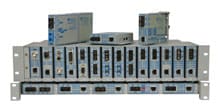
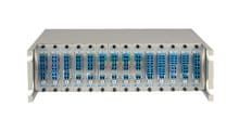
In the upper left of this diagram, UTP from a core switch is converted to fiber with a miConverter 18-Module chassis of media converters.
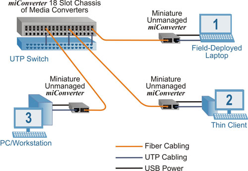
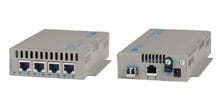
1. Fiber is distributed to a field-deployed laptop computer. A miniature miConverter media converter provides fiber connectivity to the laptop and draws power from the laptop’s USB port (represented by the black line).
2. Fiber is distributed to a Thin Client, where a miniature miConverter converts the fiber to copper and provides connectivity to the Thin Client device that does not have a fiber port. The miConverter module is powered directly from a USB port on the Thin Client device, eliminating the need for an electrical outlet and saving energy costs.
3. Fiber is distributed to a PC or Workstation, where a miniature miConverter converts the fiber to a UTP cable that is connected to the workstation supporting a 10, 10/100 or 10/100/1000 copper connection. The miConverter module is powered directly from a USB port on the PC or Workstation.
Hybrid Copper/Fiber Campus LAN
This application example illustrates an Ethernet Enterprise network with a star topology that provides multiple fiber links to remote buildings. In the upper left, three copper UTP links from a core switch are converted to three fiber links via a miConverter 18-Module chassis of media converter modules.

The fiber links run to remote buildings, where the fiber at each location is converted back to copper and distributed to end users at different buildings. Management is carried from the core switch across the fiber link to each switch located at the remote buildings. This provides centralized network management across the campus network.


